Showing posts with label File Management. Show all posts

Tuesday, November 25, 2008

Building and site files

I had always thought I had been a little pedantic when I insisted projects were set up with a building file and a separate site file. The reasons behind it are twofold.

1. If your building needs to move in the X, Y, Z coordinate during your documentation process, it is a five update minute job.

2. Due to the limitations of drawing site items in Revit, you can use detail lines and detail components in a site view. This view can then be displayed in whatever views you want in the building file.

Some would say why would you need to have two separate files when you are building on top of an existing building.

Well last week a project architect came to me. He had found an error in the surveyors drawing, where they had given the wrong level for the ground floor slab. So the entire building had been modelled 500mm higher than it actually was. So as it was set up as a building and site file, it literally was a five minute fix.

Monday, October 27, 2008

Revit on a 64Bit O.S.

It is really difficult to believe how much we are holding Revit back by having it on a 32 Bit O.S. Today I was doing some testing on of Revit 2009 (32 Bit) running a Windows Vista 64 Bit. The computer spec was a HP xw4400 with Core 2 -2.66 GHz CPU and 4 GB of RAM (not a very big computer).

I was able to have a Revit project file open of 130 MB with other files liked into it (82 MB and 62MB files). I was using Working Sharing monitor to review my CPU and RAM usage. On opening this file with links there was still nearly 1.5 GBs of RAM available. I also had, MS Outlook, MS Word and MS Excel open at the same time. I set the file up to do a batch pdf print and batch DWG export of 40 drawings. It handled it without any problems and I had no problems multitasking while Revit was working away in the background.

In a second test, I opened up a 130 MB file. Start a render of the entire building. Then open up another session of Revit and open a 40MB file and started to do you standard day to day editing. The computer handled it without a problem.

Considering the size of the computer, this is very good performance. From this, there should not be any worry about having a file size of up to 220MB on a 4GB, 64 bit computer. This can equal a building up to about 60,000 m² and documenting it right up through Construction Administration.

It is so good to think you and get so much more out of your computer by changing to a 64Bit O.S.. Revit 64 Bit just adds to this, but there isn’t going to be any jobs on Revit 2009 that will need more than 4 GBs of RAM, especially in the current financial environment. Revit now also is a lot better at shedding RAM after closing worksets. What I would say is; make sure you still manage your worksets well. When you are giving your model to your MEP or Structural Consultants, they should only need to load in the worksets of the relevant items. Obviously the more worksets a user can have turned off the faster they will work.

Monday, October 20, 2008

Review Warnings. - Part 2

There are two very good new tools Autodesk have added to assist users in removing their errors and warnings from the project.

The first is the ability to export your review warnings to an html file. This allows you view the list of warnings in any text based software, from Microsoft Word, Excel to any web browser. One of the problems when we couldn’t do before this export; was to copy and paste the element I.D.s to atext base software. This resulted in it being very time consuming when going down through a long list of review warnings. You just had to manually hand write down everything.
This new export tool allows someone like me, a BIM manager to review a project file very easly.

The second new feature is a warning button in the options bar. When an element which contains warnings is selected it appears. Click the warning icon and it displays all the warnings just associated with that element. This again can be exported to an html format. One of the great things about this new feature is you can see easily if you actually have resolved an element of not. It also gives users the ability to more easily see and fix problems that are in the file as they do their day to day editing of elements.

These two new features should really assist up in getting trough error reviews that bit quicker.

However I my opinion it is not enough. Unless errors are easy to fix, many users will not be bothered. Also you want all users to be able to fix problems, and not just the very proficient uers. So what do I recommend Autodesk add the following expansions to the existing tools:

  • Improving the “Element I.D.s” tool.
    This tool should be able to be dialog box to the side that can be open all the time if the user wishes. In this dialog box, as you select elements, you can visibly see the I.D. number of the elements. It should contain a history of the past few elements you have selected and I.D. numbers you have entered.
  • The ability to select two element number I.D.s at a time.
  • The ability to graphically isolate selected elements by I.D. in the current view. If you can isolate the two problematic elements, especially in a 3D view, you can revolve it more easily.
  • A help function in the review warnings, for each of the problems and how to resolve them. This should include images to assist new users to better understand the problem. Much of these items are in the help section already. Why not make it more accusable at a point where it will help users.
  • A direct link for the selected element in the review warnings to their element properties box. About 30% of the warnings can be fixed or partly fixed from their properties dialog box.
  • In the review warnings section the ability to graphically isolate the element of the selected warnings. (same as above).
  • The ability to have the review warnings dialog box permanently open to the side of the screen. I don’t understand why I need close this dialog box in order to fix the error.
  • Upgrading of the yellow warnings box that pops up for some errors in the bottom right screen corner is lost by click happy users. These warnings should be a proper warning box. To dismiss them you need to click “OK” and not just click anywhere randomly.
  • The user name of the user that created the error needs to be recorded with the error.
    This is not about giving blame but it gives BIM managers better information to assist users in understanding the errors they are creating. It also promotes users to fix errors so their user names don’t fill the warnings list.
  • The element warning icon needs to be made more obvious. When a problematic element is selected, this icon should have a red border. The easier users can see the problematic elements the better understanding they will have.
  • Better view creation of problematic elements. If any of you have ever used Navisworks, it does a great job of giving you a very good view in the clash detection tool. If Revit needs to create a new view to display the object is should do that.
  • There are some errors that we have to live within the project. An “accepted” section of the review warnings for these warnings would make sense. The user name could be stored with it, and an additional comment section. An example of this might me a duplicate “type mark” parameter. Due to Documentation QA procedures, sometimes it makes sense to have two duplicates.

All of the above should not be all that difficult to do. If you create a warnings system, please give us the right and best tools to resolve them.

Wednesday, October 15, 2008

Review Warnings. - Part 1


It seems it can never be underestimated the importants of clearing out as many of the Warnings in Revit as possible. It will accomplish several things and avoid the following problems:
  • A low number of warnings will keep your file size small relative to the building size.
  • Less errors means reduced computer processing and quicker completion of tasks (i.e. your model is less clunky).
  • Elements with warnings associated to them; don’t always behave correctly, be that graphically or how they interact with other elements. Removing the warnings removes this.
  • Accuracy of Schedules. No warnings ensure you have no duplicate objects or doubling of Mark numbering.
  • Some errors can cause elements not to join to other elements or inability to dimension then.

Going down though the Review Warnings is not an easy task. It takes a lot of in-depth knowledge of how categories, families and elements act. In Revit 2008 there was only two ways of resolving them.

First is fixing it when the error first happens and the warning box comes up. With the amount of clicking users do they have often passed it, before they have even seen it. Out of sight is out of mind. Right! If they did see it flash past, how do they go back to see what it is?

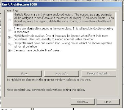
Second is to go to the Review warnings section under Tools. Here you end up with sometimes a very large list. Where do you start to resolve them? How do you resolve them? If you try to view the elements in question, often you can’t see them. Most of the time the only options it gives you it to delete the object. That doesn’t seem to be a solution.

With Revit 2009 there were some improvements in regard to assisting users sort through their warnings. I’ll come to that next post, but let’s address some of the above first.

The first item is the warnings in the first place.
So you are to click happy and you missed the warning message. Don’t ignore it. Go to the undo dropdown icon. If you have just finished a sketch you can undo the finish sketch. If you then click finish sketch you will get the ability to view the warning. In the event you were moving or dragging an element, undo what you just did and redo it. Anticipate the message and heed the warning.

Some other warning errors;
“Highlighted walls are attached to, but miss, the highlighted targets.” You can select Detach Targets or OK. Clicking OK does not resolve the problem. Detaching the target resolves it.
“A structural framing element is attached to a wall whose Structural Usage is set to Non-bearing.” You can Make the wall load baring or click OK. Again OK won’t resolve the problem. Either make the wall load baring or drag the structural framing off the wall.
“Multiple Rooms are in the same enclosed region. The correct area and perimeter will be assigned to one Room and the others will display "Redundant Room." You should separate the regions, delete the extra Rooms, or move them into different regions.” You can click Delete or OK. Again OK won’t resolve the problem. Either you delete the room or subdivide the bigger room into two.

We could go on, but you get the picture.

Going down through the Review warning.
When you are using the show tool in review warnings, if you don’t see any highlighted elements in the view, change the view to wire frame. It’s likely you will see the item.
The highlighted items themselves.
In the review warning if you click on the “Warning” it will highlight it in the dialog box. This also highlights both elements that are causing the problem. Expanding out the warning and clicking on one of the elements will highlight that specific element in the view. Clicking on the other element in the review warnings will obviously highlight the other element. This can greatly assist you in understanding the elements in question. Only tick the box beside the element if you want to delete or unjoin the element.

More on this topic in the next post.

Tuesday, August 19, 2008

Importing DWG files using Shared Coordinates.

Depending on how you have your project setup, it may be worth knowing you can import a DWG file into the project file using the project shared coordinates. You can only do this using the “link” import option. If you don’t tick link, it won’t work.

When you tick link you can select shared coordinates in the positioning pull down.

When you import the file you will get the following message:

Basically by importing a linked DWG file it will import the DWG file from the DWG’s origin point to the project Shared Coordinates origin point.

Just a word of warning:

If you Shared Coordinates origin is more then 1600 meters away from the center of our Revit project, it may not import or you may get graphic display errors in the import file.

Friday, August 8, 2008

Links and Worksharing

I can’t believe how many people I come across who are really slow to use Worksharing in a project. As a result you end up with projects being produced out of several links and are horrible and very difficult to work with.
I think the lack of confidence form users comes from being so use to working with x-refs in AutoCAD and also being unfamiliar with using shared databases, especially with-in the Architectural field. Using shared database have been used for years now in the I.T. sector and are a very proven technology. For example the Telephone IVR (Interactive Voice Response) you ring into for large companies is a shared database at the back end of it. You, however only ever get to see (hear) the front end of it.
In our office we are doing project of up to 50,000m² with one file for the building and then a separate file for the site. The thing about the file size in Revit is by the time you get to the end of contract documentation, the model itself is only about 1/3 of the file size. The rest of it comes from views / 2d information and element errors (review warnings). So by keeping your view list nice and neat, deleting unnecessary views / walk thoughts, regularly clearing out the warnings, purging, not using large raster images, and doing compressed saves one a week you will keep you file size down.
These days you only have to start to get concerned when the files size it getting well over 160MB. And even then you should be fine.
So the point of the above:
Worksharing and worksets (model break up, ie façade, structure, roof, service elements, furniture fittings and equipment and so on) is an amazing tool for sharing a project and breaking in into more workable parts. Links are also an amazing little tool, but only use it where it is appropriate, i.e. for each separate building and site.
If you do end up with a large file that is giving you problems in being slow or crashing, by dealing properly with the “review warning”, it will cure the problem 90% of the time. For the other 10% it will be a computer or network problem.

Thursday, July 31, 2008

View Naming Convention.

One of the main things you need to consider when coming up with a naming convention for view is ease of finding them. This especially comes up when you are using the cross view reference tool “Reference other view” (i.e. with a detail section or call out). All of a sudden you have to sift thought every single view in your project, and when it that comes to a large project in contract documentation, that could be up to 1000 views. A real nightmare1

My suggestion is to name you views by the sheet numbers they are placed on, followed by its detail number on the sheet, and finally by a short view description.

This is the only way to really manage cross reverencing in large projects.

Example:

Sheet No. A1045, Detail 4, Plan of joinery unit J16
View name : A1045-04 PL Join J16

Do keep the view name less than 30 characters; other wise, you will need to have the project browser very wide.

Monday, July 28, 2008

Revit Extensions

So you may have seen that Autodesk have added a plug-in to Revit Architecture 2009 on the Subscription Website.

Extensions are a series of several little add-on tools. Some of these tools may end up to be useful. The Compare models, Element positioning, Freeze drawings and Text Generators look like they could be quite helpful.

Find some images below.
Like everything in Revit, really getting to understand the tools will allow you to know when is a good situation to use them.


Tuesday, July 15, 2008

More on Columns

I had forgotten this point on Architectural columns when I talked on this subject last time. That is, Architectural Columns are not on the list of categories that can be scheduled.

You can in theory schedule them using a multi-category schedule, but you don’t have the same flexibility

Here is an example of how you can schedule structure columns. It allows you to create a very quick way to coordinate with the engineer but also edit the start and stop points of columns very quickly, and your understanding of the building.

Tuesday, July 1, 2008

AutoCAD linked into Revit

A list of issues in linking AutoCAD files into Revit

  • Not all AutoCAD line types can import into Revit – eg Insulation – Customised AutoCAD line types with symbols and text.
  • Arrows on leaders and dimensions some times do not display properly in Revit. One solution is to ensure all leader arrow head are a block with-in the dimension leader.
  • Linked AutoCAD items can not be used to dimension off as if the link path becomes broken, the dimension, will be deleted.
  • When doing milestone archives in Revit (for future Revit version ease of compatibility) all AutoCAD linked files need to be removed. Thus the intent of having them in there in the first place is lost.
  • Each AutoCAD files should only be linked into one view, or all the views. In the event it is only in one view, when it is turned off in that view it can be near impossible to find which view it has been linked into. In the event you link it into every view, you then have to manually turn it off in every view. Never copy a linked file within Revit. When the original one is removed the copied link will also be removed.
  • When creating dwg files for Revit Views, you need to create a separate detail AutoCAD file for every view. This is required for proper cross referencing. General AutoCAD users won’t be aware of this so you will need to ensure you inform them.
  • When creating dwg files to be linked into Revit every element must be drawn by layer. It is also important that dwg files linked into Revit Drafting views should not contain any additional drawings or old details out to the side, as drafting views can not be cropped. Really it is good practice to remove these kinds of old details to the side from all AutoCAD linked files.
  • Avoid linking dwg files that have xrefs within them. Other that an uncertainty of if they will view properly, in the event they become corrupt, you might have difficulties in opening your Revit file.
  • Currently there are some know bugs with exporting views/sheet that have linked AutoCAD files. The link does not end up exporting. This seems to happen on large links (area), and resolutions include turning off the crop region of the view.
  • Excessive AutoCAD linked files can slow down opening time of the Revit project file.
  • AutoCAD dynamic blocks using visibility setting in links may become distorted once imported into Revit.
  • Some AutoCAD hatches will not appear correctly when imported or linked into Revit. The only solution is to explode them in AutoCAD or use a different hatch.
  • AutoCAD files with shx fonts may not appear correctly when linked into Revit. The solution is to map your .shx fonts in AutoCAD to Revit TrueType fonts by editing the file "shxfontmap.txt" (which you can find in the "Data" Folder of your Revit Architecture installation directory, - C:\Program Files\Revit Architecture 2008\Data). To edit this file, first type in your Autocad .shx font you are using in your drawing and give a space/tab and type in the TrueType font you want to use in Revit.
  • AutoCAD linked files containing AutoCAD text symbol shortcuts (this includes underlines and degree symbols) will not appear correctly in the Revit view.
  • Large AutoCAD linked files into Revit can generate the following Display Error: “An error has occurred while drawing the contents of this window. This window shall be closed”. The result is the file crashes.

Quite a long list isn’t it! Yet the Autodesk sales person how tries to sell you Revit will tell you AutoCAD is 100% compatible with Revit. To be really honest, there are very few software packages out there that are 100% compatible in regard to file transfer. From the above, most of the issues comes up with shot falls in AutoCAD and how it codes it’s file. The upside it that Autodesk did learn it’s lesson that backward compatible files, means bad programme decisions in the past are near impossible to correct. So the question really is; how should you use dwg files with Revit?

General Recommendation

Links are great for reference /coordination files where you won’t be printing them out as part of your drawing set. When you have finished your reference / coordination (ie with the structural engineer or mechanical / electrical engineer) remove the linked file.

Avoid using dwg linked files where the dwg is going to be updated throughout the current stage of the project. You can just never guarantee it will print out correctly every time. The idea of doing 2d work in AutoCAD and linking it into Revit is a copout to learning Revit and from above is plagued with possible problems. 2D detailing in Revit is easy and when you get your head around it quicker than AutoCAD.

Importing a dwg is not the end of the world. Personally, I recommend it for site survey plans. Ensure the dwg file is fully cleaned up before importing (purge, logical origin, remove hatch patterns, change all text to Arial, remove leaders and dimension, remove un-necessary lines, flatten, minimise layers, ensure all the lines are on the correct layers ect). The thing is when you import it and explode it, if items don’t display correctly, you can fix then and there, and be 100% confident it will print out and reference correctly in the future. These new imported exploded items now become Revit lines, and thus can be edited and updated.

Thursday, June 19, 2008

Slightly off axis

“Element is slightly off axis and may cause inaccuracies.”

How often do you get the above warning? So what exactly is it!

From the help file:

Problem: This warning is triggered by elements based on lines that are misaligned —by 1x(10^-9) to .2 degrees— with either the horizontal or vertical directions, or with a line at 45 degrees to the horizontal/vertical direction.

The problem can be caused by sketching or rotating elements when angle snaps are turned off, or it can result from pre-existing elements when you do any of the following:

  • Create an element by picking a slightly off-axis face or line.
  • Align an element to a slightly off-axis reference.
  • Explode an AutoCAD import that contains slightly off-axis lines.
  • Create floor area faces on a mass that has slightly off-axis geometry.
  • Snap defining line ends to references that are slightly off-axis (such as imported drawings or 2 columns that are not properly aligned).
  • Snap defining line ends to references that are positioned correctly in their respective contexts but the line between them is slightly off-axis (such as snapping to 2 different ceiling grids).

Off-axis problems need to be resolved, because Revit Architecture cannot create dimensions between lines that are not exactly parallel, and cannot join or cut geometry if faces are slightly off-parallel or have very small gaps due to off-axis elements.

Solution: Depending on the cause of the problem, do one of the following:

  • Drag the end of the off-axis element a short distance and let it snap to the axis.
  • Repeat the rotation operation with angle snaps turned on.
  • If the inaccuracy is derived from pre-existing elements, correct them and repeat the operation.
  • If the problem is caused by imported data, consider correcting it in the original software and re-importing it into Revit Architecture.

Sunday, June 15, 2008

Why is my Revit file so BIG?

So you have been handed over a Revit project file for you to start design development or contract documentation. You look at the file size; 95 Mb. You open the file and have a look at the project. You think to your self; “How is this file size so big, the building is quite basic?”

So the first thing you do is spend 15 minutes purging the file. You then do a compressed save. Look at the new file size; 87 Mb. You ask your self, “This is not right”.


(A light bulb goes off)

Have a look to see what Raster Images are in the file. There are 7 in there. “Bingo”. Remove them and your file is down to 35 Mb.


Punch line.

Raster images are great, but they need to be managed and when used ensure the imported images are as small as possible with in the graphic quality range you require. We documenters sometimes forget how much designers use images in sketch design stage.