Just a tip on using the resize command, if you had to create the element using sketch mode, to resize it, you will need to go back into sketch mode for this command to work (some what logical). An example would be; you can resize lines at any time, but in order to resize a “filled region” you will need to select the filled region, hit Edit on the Options bar and then you can resize it.
Saturday, June 28, 2008
Resize = AutoCAD’s command for scale.
“Lines” – Oh wait; they are actually model lines.
It has to be admitted that Autodesk really need to review some of their naming terminology in Revit. The above “Lines” command is definitely one. In the Basic design bar when newer users see “Lines” they don’t know what type of line it is? Well it’s a model line, and really Autodesk should change the name Lines to Model Lines here to avoid confusion. After all when you select the line, it is called a “model line” in the status bar.
My other pet peeve is, can they make up their mind if Detail Components are called components or items? In the design bar they are called components and in the family browser they are called items. It’s not that difficult really!
Monday, June 23, 2008
Fire Egress Distances
This is a great little help from Revit OpEd on assisting you with your fire egress distances. Nice little family Steve. Thanks.
Revit OpEdSome differences between “Columns” & “Structural Columns”
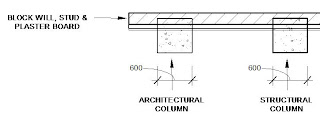
For an examples I have created a 600x600mm concrete (Architectural) Column and a 600x600mm concrete Structural Column. The wall they adjoin is a 200mm Block wall, with a stud lining and plaster board finish.
The walls have just been inserted in the shown location. They look fairly normal.
Now let’s hit join geometry on hitting the column first and the wall second. I bet you didn’t expect the architectural column to do this!
A few things should be noted.
1- The architectural column takes on the hatch properties of the core of the wall.
2- The architectural column also takes on the wall make up properties, ie stud and plaster board.
Now there are some circumstances where you will want this to happen. Hover there is more incidences where you won’t. What’s more with “Architectural Columns” they seem to have an uncanny knack of joining geometry with elements intersecting it, even if in the family the “Automatically joins geometry” is un-ticked in the column family parameters, thus its cut pattern does not view correctly in plan.
Structural columns.
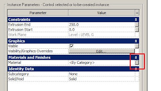
The out of the box Revit Architectural columns do have their flaws but they are fixable. First the material type is set to a “Instance Parameter” in stead of a “Type Parameter” (easy to change). The next issue is that the “Show Family pre-cut in plan views” is automatically turned on in the Family Parameters. By switching this off, you can set the column to appear in grey or black in course scale plan views.
After the above fix, generally I recommend people use structural columns for structural usage, and if you have a no-load bearing column us an (architectural) column.
Sunday, June 22, 2008
Thumbnail previews with Revit 2009 & Vista
Well done Autodesk. I can see the issue that most Revit 2008 insulations had with Windows Vista in getting Revit files to have a thumbnail preview has been resolved with Revit 2009.
For the majority of large offices that confine them selves to Windows Exlporier this is a really great. Trying to navigate libraries with out thumbnail previews is very difficult.

Thursday, June 19, 2008
Slightly off axis
“Element is slightly off axis and may cause inaccuracies.”
How often do you get the above warning? So what exactly is it!
Problem: This warning is triggered by elements based on lines that are misaligned —by 1x(10^-9) to .2 degrees— with either the horizontal or vertical directions, or with a line at 45 degrees to the horizontal/vertical direction.
The problem can be caused by sketching or rotating elements when angle snaps are turned off, or it can result from pre-existing elements when you do any of the following:
- Create an element by picking a slightly off-axis face or line.
- Align an element to a slightly off-axis reference.
- Explode an AutoCAD import that contains slightly off-axis lines.
- Create floor area faces on a mass that has slightly off-axis geometry.
- Snap defining line ends to references that are slightly off-axis (such as imported drawings or 2 columns that are not properly aligned).
- Snap defining line ends to references that are positioned correctly in their respective contexts but the line between them is slightly off-axis (such as snapping to 2 different ceiling grids).
Off-axis problems need to be resolved, because Revit Architecture cannot create dimensions between lines that are not exactly parallel, and cannot join or cut geometry if faces are slightly off-parallel or have very small gaps due to off-axis elements.
Solution: Depending on the cause of the problem, do one of the following:
- Drag the end of the off-axis element a short distance and let it snap to the axis.
- Repeat the rotation operation with angle snaps turned on.
- If the inaccuracy is derived from pre-existing elements, correct them and repeat the operation.
- If the problem is caused by imported data, consider correcting it in the original software and re-importing it into Revit Architecture.
Wednesday, June 18, 2008
Shadows and Filled Regions.
If you are using shadows in views, care needs to be taken when using solid filled regions. The issue arises when solid filled regions are set to transparent. You may end up getting the following error “Shadows will not display if filled regions are set to foreground. Set filled regions to background". If you do get this message (some times you won’t) you will notice your shadows will not display or only partly display. The solution of course is “don’t use transparent solid filled regions in views you want to use shadows”. This issue is currently with Revit 2008 and it appears to be fixed in 2009.
Tuesday, June 17, 2008
Managing materials in “In-place families”.
The Associate Family Parameter dialog box will open up. Select “Add parameter”.
The Parameter Properties dialog box will open up.
Enter the name – Material. Select “Materials and Finishes” in the group parameter box, and select the "Type" button. You will see the type of Parameter is default set to Material. Click OK and finish the family.
It may be a few more clicks of the mouse at the start, but it allows you to change materials very quickly.
Hatching on curved elements.

Today I came across directly how bad Revit 2008 is at putting hatch surfaces on curved faces. (left image). In fact some times it doesn't at the hatch at all.

It is one the of items that has been fixed Revit 2009 (left), but it’s not exactly perfect (you can see from the image), buts it’s not really possible to rotate the hatch.
The two pictures show a model hatch.
Monday, June 16, 2008
Line work tool in perspective views
I was a little frustrated today to find out the line work tool does not work in perspective views (Revit 2008). I was happier to see just now that this has been fixed in Revit 2009 build 20080602_1900.
The work around I had to use today with the above problem, I had promised myself I would never use. Because in perspective views the filled regions or masking regions tools don’t work, I had to go into the plot sheet and cover the undesired line with a white line. First and last time I hope.
Sunday, June 15, 2008
Why is my Revit file so BIG?
So you have been handed over a Revit project file for you to start design development or contract documentation. You look at the file size; 95 Mb. You open the file and have a look at the project. You think to your self; “How is this file size so big, the building is quite basic?”
So the first thing you do is spend 15 minutes purging the file. You then do a compressed save. Look at the new file size; 87 Mb. You ask your self, “This is not right”.
(A light bulb goes off)
Have a look to see what Raster Images are in the file. There are 7 in there. “Bingo”. Remove them and your file is down to 35 Mb.
Punch line.
Raster images are great, but they need to be managed and when used ensure the imported images are as small as possible with in the graphic quality range you require. We documenters sometimes forget how much designers use images in sketch design stage.
Design options – Hide /Unhide in view
Here is an interesting little thing. If you have someone working with design options in our project, and there is something in the design option that you want to hide in a view, you have to open up the design option first before you can select that item to hide or unhide in the view. With all the different things you have to think of when you are having visibility issues, this is just one to add it.
Friday, June 13, 2008
Color Schemes R2008


Color Scheme turned on. - Furniture form the lovel below is showing through.
Well, it has to do with how floor entities behave when color scheme is activated in a view. It caused floors to become transparent, and thus if your view dept is below the slab you will see everything in the view dept which is suppose to be hidden by the floor slab.
What’s more is it does not just make the floors transparent, it also brings any floor entities which are less than 1200mm below the associated level up to the view range. Thus, if you were using the old way of drawing your concrete beams as floors, they will come out on your color scheme, even with the view dept set to the associated level.
So the workaround:
This is a difficult one. On a large job you could spend hours hiding elements in views you don’t want to see. My general recommendation is to set the view dept to the associated level. If you are still seeing floor entities, turn off the floor category in visibility graphics.
If you need to set up a view where you want to have the view dept going down to the level below, I suggest you create a separate plan of the level below for this function. In its view properties set it as an underlay. Place this view on your drawing sheet, and then place the color scheme view (as per the above view dept settings above) over it.
It’s not ideal and if you have a split level floor you still may have view issues.
Unfortunately this is just a big bug and difficult to get a workaround that will fix every instance.
Revit 2009 is the only real solution.
(P.S. if you ever used the make item transparent in color schemes so the color fill is in the background, it won't work in 2009).


